Visual programming with graphsFlow Engine & Editor
This chapter covers the following topics:
Flow Editor Overview
The Flows section provides functionality for the creation and management of Flows. It is divided into the sections

Sidebar
The sidebar provides a tree view that displays all Flows and packages. The default “Flows” entry acts as a root element that groups all elements. Left-clicking a Flow element in the tree will load it’s content into the canvas view and set it as active. Right-clicking elements in the tree view provides a context-menu that allows access to various functions.
When the root element is right-clicked, it will provide the option to create a new Flow or package. For Flow elements the menu will provide the option to rename or delete the currently selected flow. Packages can be renamed and deleted as well as providing the option to add new child Flows or packages. Using drag-and-drop on the icon of Flows or packages, existing elements can be moved in the tree hierarchy.
Canvas
If a Flow is selected, it will be rendered on the canvas area of the Flows section. The context menu in this area provides the option to create new Flow nodes from the categories “Action Nodes”, “Data Nodes”, “Logic Nodes” and also offers shortcuts to run the active Flow as well as managing it’s layout. Each existing Flow node will be displayed with it’s type as title and the available connection sockets. The left hand side of Flow elements displays all available input sockets and output sockets are found on the opposite side.
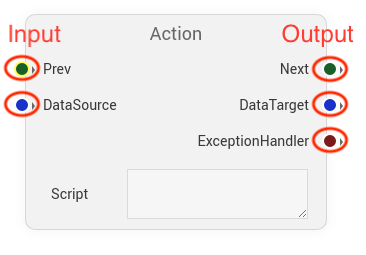
Elements can be moved using drag-and-drop on their title bar. Drag-and-drop between an output socket of one node and the input socket of another node allows the creation of connections between Flow elements. These connections and also the respective sockets are color coded to signal their purpose and compatibility. Green connections and sockets represent execution Flows, which in turn show the path a Flow will take when being run from start to finish. The starting Flow element can be identified by it’s green title bar and elements can be set as such via the right-click context menu, if they are applicable as starting element.
Connection Types
Green connections between elements represent the execution flow. Blue connections between elements represent the Flow of data. Orange connections represent conditional and logic Flows that are used in conjunction with Decision elements. Brown connections represent connections between flow elements and their exception handler element.
Menu Bar
The menu bar above the canvas area provides shortcuts to some of the functionality that can be found in the context-menu of the canvas. The input field and “Add” button allow the creation of new Flows and the adjacent “Delete Flow” button deletes the currently active Flow. The Flow layout manager can be opened using the “Layout” button and the current view position and scale can be reset using the “Reset view” button. Lastly the active Flow can be run using the “Run” button. The result will be displayed in a popup in the top-right corner of the Flow area.
The “Highlight” selector allows highlighting the different connection types between flow elements to get an easier overview of the flow. The highlighted connection type is drawn thicker and the other types are drawn thinner while the highlighting feature is active.
Working with Flows
In this section we walk you through the different steps involved when working with flows.
Creating Flows
The first step is to navigate to the Flows page. Hover over the hamburger menu item in the Structr navigation bar and select Flows. Once the editor is loaded, you can either select an existing flow to edit or create a new one. For the sake of this introduction, we will create a new one. To create a new flow, enter a name of your choice in the input field and click the Add button.
Alternatively, you can also create a new flow by right clicking on the root element of the flow-tree in the sidebar, or on a given package, and selecting “Add Flow” as described in the section above.
To keep Flows more organized, they can be grouped by packages. New packages can be created via the context menu in the tree view on the left hand side of the editor. Once created, flows can be organized by drag-and-drop. It is important to note that a Flows effective name will be generated from the package hierarchy. A Flow called “flow1” in the package “package1” will result in the effective name “package1.flow1”. This combined name can then be used to call flows from scripts:
$.flow('package1.flow1', {
    'parameter1' : x,
    'parameter2' : y
})
Using the context menu
A new flow starts out blank and will not have any contents. To start adding new elements, bring up the context menu by right-clicking on the canvas and select an element to add to the flow. The context menu can also be used on existing elements to bring up specific options, such as removing nodes or setting them as the entry point of the flow.

A complete overview over all existing flow elements can be found in the
Creating Flow elements
For the sake of this demonstration, a simple flow with an Action and a Return element is created. Both of these can be found under the Action Nodes category of the context menu. The first viable start element added to the flow will automatically be marked as such. A start node or flow entry point is indicated by the green coloring of the node header. The start node can be changed by bringing up the context menu on an element, if it is viable a menu item called “Set as start node” will display.

Editing scripts within Flow elements
To add functionality to the flow, we will add a small StructrScript snippet to query existing users in the database. Left-click the Script text box of the Action element to bring up a code editor and enter the script as shown below.
Connecting flow elements
Now that our Action contains a script, we want it to return its result. For this to happen we have to make sure the flow execution does not stop at the Action element. Drag a connection from the “Next” socket of the Action element to the “Prev” socket of the Return element to create an execution flow, indicated by the green color of the connection. Our function is now capable of returning something after the Action has been dealt with, but at this point in time, it will return an empty result, because we have not yet connected data to the Return element. In the same way the first connection was handled, create a connection between the elements “DataTarget” and “DataSource” sockets to create a data flow. When a node is being evaluated by the engine, it will try to consider connected data flows and make them available within its scripting context in the example of an Action or Return element.
Running Flows
With everything set up, it’s time to test the flow. Use the Run button in the top right corner to let the flow execute and display it’s results.
Using Flows in Scripts
Flows can be called from any serverside scripting context using the in-built flow() function. The function is supplied with a reference in the form effective name and optional parameters as alternating key-value-pairs (or a parameter map in JavaScript).
In this example a flow is bound to an entity’s FunctionProperty read function and as such the flow would be evaluated every time the property is read.

Calling Flows within Flows
Besides calling flows from a scripting context, it’s also possible to reuse flows from within flows by using the FlowCall element. This allows the user to select a flow from all existing flows and optionally supply parameters to the call as well. In the following example a very basic use is illustrated.